Dear customer,
Thank you for ordering the repair kit for Renault Scenic 2 or Espace 4 cluster.
In most cases, the MOSFET transistor is short or broken because of an overheating. It must be
replaced. It is located under the display.
The most delicate step is to desolder the display:
- Desolder every pin one by one with a desoldering pump.
- Use a desoldering braid for residues and the hardest solders. There must be no solder at all around
the pin and inside the pad so it moves freely.
- First lift delicately the side of the display with the fewest pins.
- Display facing you, make several torsion movements with the display to unstick and « crack » solder
all along the long row of pins on component side.
- Now lift the long row VERY DELICATELY starting by one side.
Pay attention not to peel the tracks! Ask a professional of electronics if you can’t succeed. You will
get to that point:
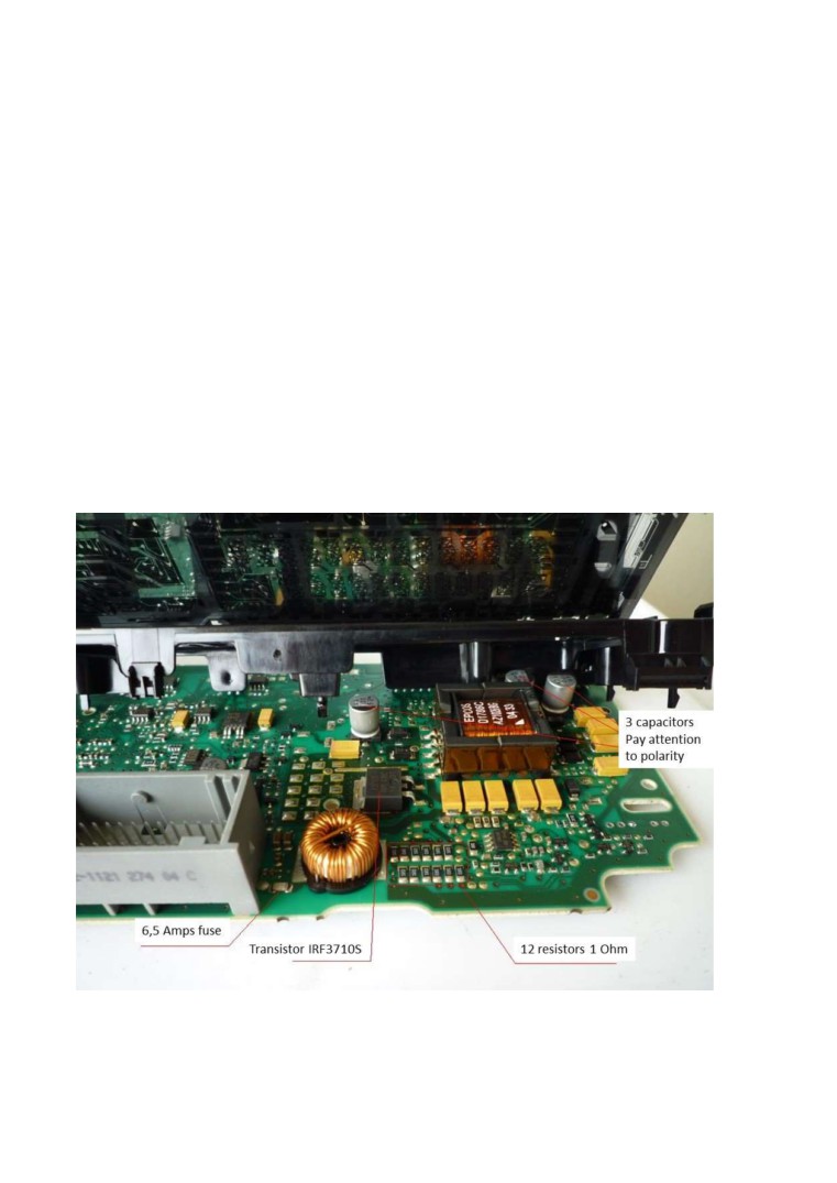
Replace the needed components as stated on the picture.
It’s better to work under a magnifier. Respect the polarity of capacitors!
Tips:
- For easy removal of the IRF3710S, first cut the pins and then desolder the two pins.
- Then heat the back of the transistor by heating the big pad and adding fresh solder that will help
propagate the heat. This will help the removal.
- Clean well the excess solder with desoldering braid to get a flat surface back.
Put and solder the MOSFET on the PCB without excessive heating
(Temperature 300°C to 350°C for 10 seconds).
Redo every solder in the area all around the MOSFET and the PWM (8-pin component hereafter).
The transistor heats the components in this area, so they end up unsoldered with time:
IMPORTANT: All the components in the kit must be used: transistor IRF3710S, the 3 electrolytic
capacitors (pay attention to polarity!), the fuse and the 12 resistors.
IMPORTANT: Once repaired, the cluster must be tested on the vehicle by plugging the grey and red
connectors. The cluster will not switch on by just connecting it to a 12V power supply on pins 1 and 2
of the grey connector.
If in the end the cluster does not switch on but the clock works normally, then it is possible (though
very rare) that the display itself is burnt or the microcontroller is “bricked”.
Good luck for your repair!
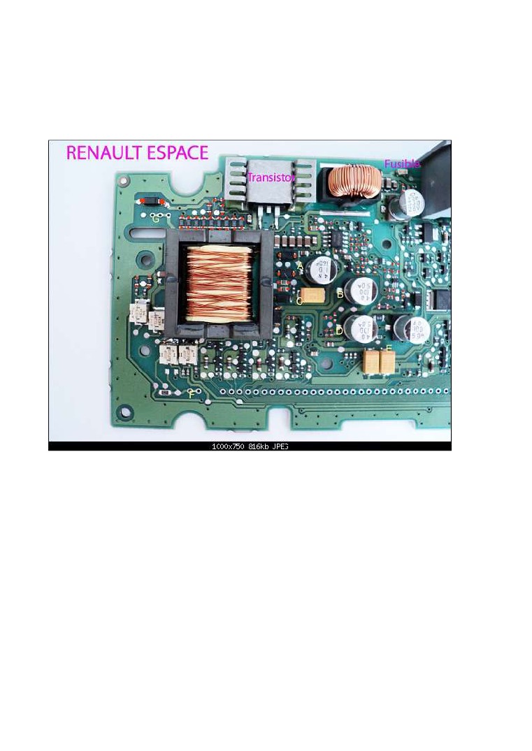
Espace 4 version :
The position of parts is different on Espace 4. Then please refer to this image that shows with red
dots the solders that need to be redone:
The capacitors to replace are those that sit the closest to the transformer, which are marked A, B, and
D on the image (100uF, 50V) and the one close to the fuse (330uF, 25V).